Analysing pavement widths using OS Select+Build
Examining the methodology behind the creation of pavement widths data
Following on from the success of the TfWM project, this piece details the output from that work, illustrating the methodology that can be used to determine pavement widths. This methodology creates transects by using data from the OS National Geographic Database (NGD), accessed using OS’s new personalised and simplified OS Select+Build tool.
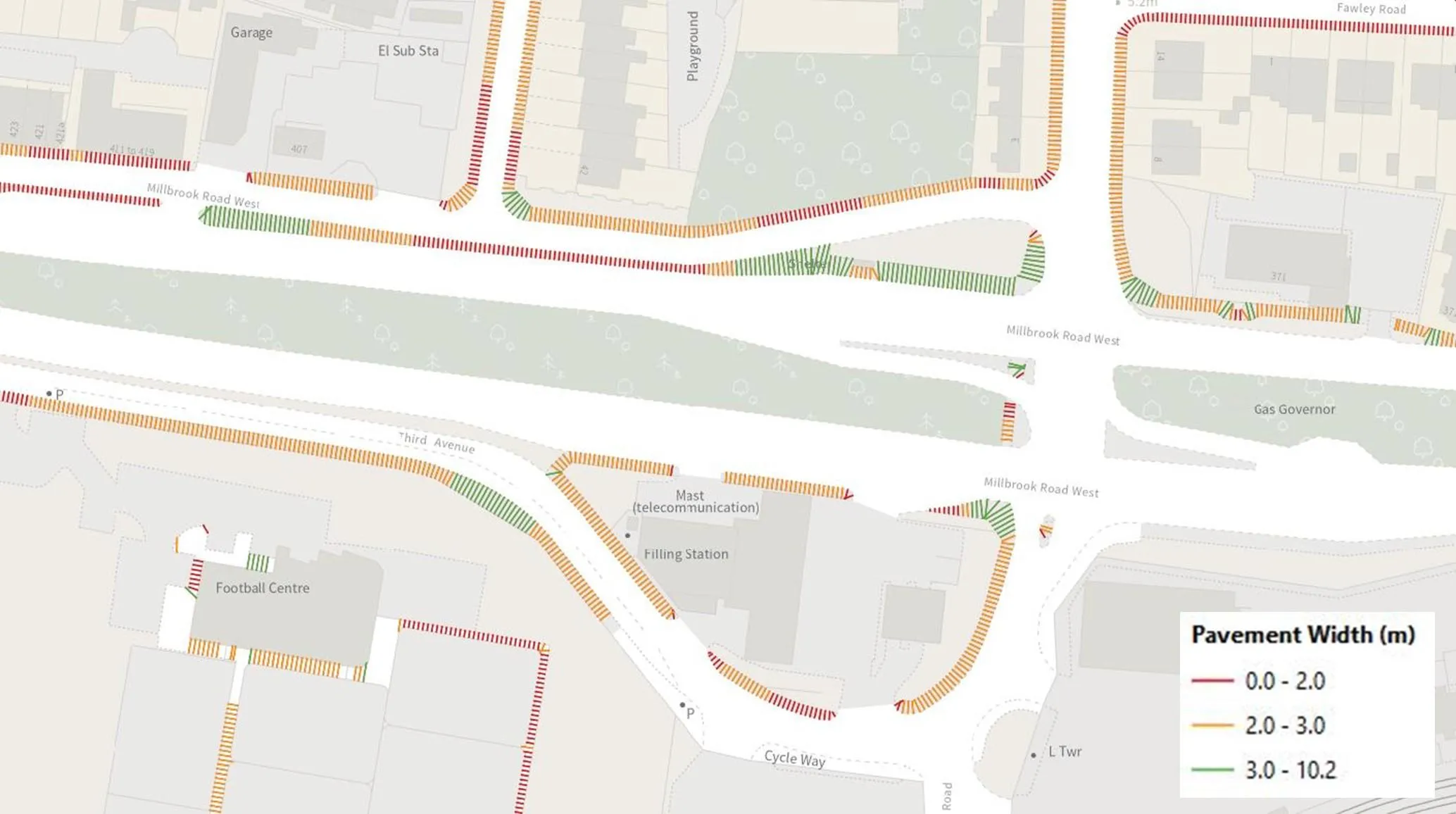
Pavement widths and the ability to measure them quickly and accurately has received increasing prominence in recent years. Research from Esri, using measurements from OS, revealed that most pavements in Great Britain were less than three metres wide, making it hard for people to socially distance during Covid-19.
However, the following methodology isn’t just suitable for pavements. Using OS data you can adapt this methodology to calculate widths of other features like rivers, roads and grass verges.
Methodology
To simplify this the methodology has been broken down into three sections: data, published parameters, and method overview. The method uses the following software and data:
- Feature Manipulation Engine, known as FME (it’s recommended that you have version 2020.0.1.0 or later)
- OS NGD data
FME was the chosen software as TfWM had existing access to it as well as very good internal capabilities using it.
Data
OS NGD data is used because of its detailed attribution and ease of filtering pavements and paths from the Transport Features theme. The FME workbench uses OS data in a GeoPackage format.
How to access this OS data:
Create a recipe in OS Select+Build on the OS Data Hub by expanding Transport theme > Transport Features > Road Track Or Path.
- Apply a filter to this data to include ‘Path’, ‘Path and Steps’, ‘Pavement’, ‘Pavement and Steps’.
- Create the recipe. You will then need to create a data package in a GeoPackage (GPKG) format (as this is what the FME workbench uses) for the area you require. We’ve used GeoPackage because of its plug-and-play nature, but other formats can be used if the workbench is adapted.
Published Parameters
The published parameters are variables created to make using the workbench easier and allows values to be easily changed depending on the project. Below is an explanation of each of the parameters, along with their default values. All parameters can be changed by using the dialogue box that appears when you begin running the workbench.
- AOI name: for ease of identification, the user is prompted to give the Area of Interest a name. This is used in the file name of the dataset that is produced.
- AOI file location: a directory prompt for the location of the Area of interest (GPKG). This can be any size but smaller areas will run significantly faster.
- OS NGD Paths and Pavements file location: a directory prompt for the location of the OS Select+Build NGD pavement and path data downloaded from OS Data Hub. This needs to cover the whole of the area you are looking to analyse.
- Transect Spacing: the distance (metres) between transects along pavements and paths. By default, this is set to 1m as it provides a good level of granularity but can be changed if required. A lower number will result in more transects.
- Line Extension in metres: this is how long the transect lines are extended across pavements and paths before they are clipped to the underlying polygon dataset. The default has been set as 10m because it provides coverage in most situations, whilst keeping the process fast. It can be set between 5m and 30m if required which is useful when dealing with particularly wide and large pedestrian areas.
- Allowable Overlapping Lines: due to complex geometries and how the underlying data is collected there are instances where transects pass over others, such as tight corners, dead end streets and cul-de-sacs. The analysis output can look complicated and cluttered, but by setting the maximum allowable overlaps to a low number, transects across features such as road bends can be retained whilst transects that are the result of odd shapes are removed. By default, this is set to 3 as it provides a good compromise, but this can be changed in this parameter if required.
- Output Centre Lines: this is a prompt which allows you to choose whether to extract the centre line as a line geometry.
- Save Location: a directory prompt for file save location. The file will be saved here named 'AOI Name' pavements_'todays date' as a GPKG. The format can be changed in the feature writer.
- Advanced Analysis (optional): an optional addition to the workbench that allows you to remove any transects that do not intersect either edge of the path/pavement. Select 'yes' if you would like this.
Method Overview
This next section provides a brief overview of the methodology within the workbench.
The pavement and path GPKG from OS Select+Build and the AOI are read into the workbench.
Generating the centreline & transects:
- A centreline is generated from the Path and Pavement polygon from OS Select+Build in order to create the transects.
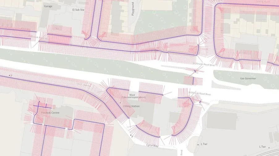
- Transects are created at a user specified distance (see transect spacing parameter) along the centreline and rotated 90 degrees across the Path and Pavement features.
- Transects are extended to a user specified distance (see line extension in metres parameter) either side of the centreline so the full cross-section of the polygons are captured.
- Transects are then clipped to the pavement/path data and any remnants are removed.
Transect Testing
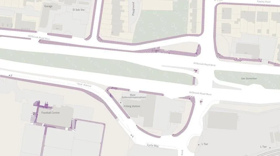
- Transects are tested by checking to see if a transect intersects its own centreline. If it does, then it passes.
- If a transect crosses too many other transects, it is removed (as set in the allowable overlapping lines parameter).
Data Output
- The data is appended with the transect width figure in metres based on the Transect ID.
- A single GeoPackage is created with a name based on the AOI Name parameter and date.
If you’d like to access the detailed methodology and the FME workbench used for this project then please go to the OS GitHub page.
Two workbenches have been created. The first uses the FME 2020 release, and the second using FME 2022. This is due to a slight change in the transformers process between the versions.
Please note: This is a methodology and not an OS product. The methodology can be taken and adapted, but OS will not be maintaining this methodology.
Benefits of the OS Data Hub
Whether you’re new to geospatial or a GIS data expert, the OS Data Hub grants access to our data. Discover our platform and the benefits of using it, along with an explanation of the types of GIS data you can get.

Our highly accurate geospatial data and printed maps help individuals, governments and companies to understand the world, both in Britain and overseas.
Find more blog articles
- Built environment
- Innovation
- Transportation infrastructure
- Great Britain
- United Kingdom